INFORMATION
Description
According to the Next Generation Broadcasting (NGB) planning and PON standards, 1550nm is defined as the transmission wavelength for HFC downstream.
The high cost of 1550nm external modulated transmitter and dispersion effects of 1550nm directly modulated make network transformation difficult. Thus we create the 1550nm directly modulated optical transmitter with electronically controlled dispersion compensation.
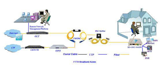
It supports up to 1.2GHz band and DOCSIS 3.1 system. With two RF inputs and high isolation, it enables the signal transmission of QAM and IPQAM smoothly. Support a transmission distance of 50KM with electronically controlled dispersion compensation. Built-in CWDM is optional for multi-wavelength networking.
Performance Characteristics
- 1.2GHZ band, support DOCSIS 3.1 system.
- The AGC and MGC gain control modes are optional.
- Two inputs with 50dB isolation for high quality RF insertion.
- Dual power supply; hot backup; a variety of power supply options are available, optional AC220V and DC48V.
- Laser output power, bias current and cooling current are detected in real time.
- Optional CWDM for optical signal insertion.
- Electronically controlled dispersion compensation can support a transmission distance of 50KM.
- Low-cost solution is comparable to the performance of external modulated transmitter.
- ITU standard wavelength is optional.
Technique Parameters
Item
|
Unit
|
Parameter
|
Optical part
|
Optical wavelength
|
nm
|
ITU wavelength
|
Laser type
|
|
Butterfly-typed DFB laser
|
Optical modulation mode
|
|
Direct optical intensity modulation
|
Optical connector type
|
|
FC/APC or SC/APC
|
Output optical power
|
mW
|
10
|
The insertion loss of the VOA and CWDM is excluded.
|
External optical signal input
|
dBm
|
-5~10
|
RF part
|
Frequency range
|
MHz
|
47~870/1003/1218
|
RF input level
|
dBuV
|
77± 5
|
Flatness in band
|
dB
|
± 0.75
|
Input return loss
|
dB
|
≥ 16
|
RF AGC control range
|
dB
|
±5
|
RF MGC adjustable range
|
dB
|
0~20
|
RF input isolation
|
dB
|
≥ 50
|
Isolation between two RF inputs
|
RF input test port
|
dB
|
-20±1
|
Laser drive level test port
|
dB
|
-20±1
|
Electronically controlled optical attenuator tolerance
|
dB
|
≤1: ATT 0-15dB
|
≤3: ATT 16-20dB
|
CNR
|
dB
|
≥ 48
|
550MHZ 59CH analog signal 77dBuV/CH
550-870MHZ 40CH digital signal 67dBuV/CH
25 Km, -1dBm input
|
C/CSO
|
dB
|
≥ 58
|
C/CTB
|
dB
|
≥ 63
|
CNR
|
dB
|
≥ 46
|
550MHZ 59CH analog signal 77dBuV/CH
550-870MHZ 40CH digital signal 67dBuV/CH
50Km, -1dBm input
|
C/CSO
|
dB
|
≥ 55
|
C/CTB
|
dB
|
≥ 63
|
MER
|
dB
|
≥ 40
|
25 Km, -1dBm input, 96CH digital 77dBuV/CH
|
≥ 39
|
50 Km, -1dBm input, 96CH digital 77dBuV/CH
|
Others
|
Maximum power consumption
|
W
|
≤10
|
Operating temperature
|
℃
|
-5 ~ + 55
|
Storage temperature
|
℃
|
-30 ~ + 70
|
Weight
|
Kg
|
1 |
Application

Ordering information
Related Products
